Introduction
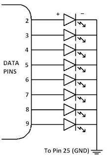
In this article I will first tell you about how to build the LED interface circuit for the Parallel Port and then how to control the circuit using software. With this very basic prototype you will be able to learn a lot how the parallel port works. So, I'll start with the circuit first.
Circuit Diagram

Circuit Description
Components Used:-
- Eight RED colored LEDs
- DB-25 Male Connector
- Zero PCB
- Ribbon Wire
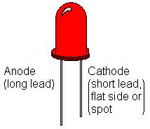
Since LEDs have polarity, you should pay attention to correctly locate its positive and negative terminals. If you pay close attention, you will see that LEDs are not completely rounded, the cathode side is a little bit flat. Also the longer leg of LED is anode or positive terminal and the shorter leg is cathode or negative terminal.

How the circuit works?
Working of this circuit is pretty simple. When data at any pin 2 - 9 is '1' , that particular LED will glow, else if data is '0', the LED will stop glowing.
When data at any pin from 2 - 9 is '1',then it means that 5 volts is coming out of that pin and is going towards +ve terminal of LED. Circuit gets completed through ground pin (any from 18 to 25) and the LED glows until data at that particular pin is not '0'.
This data flow is controlled using software discussed below.
Software
To control any port we need a kernel mode driver software. Softwares generally run in USER mode. But to control the Parallel Port we need a software running in kernel mode. I have used C#.Net for developing this software.
- Download and install Microsoft .NET Framework Version 2.0.
- Now download and install My Parallel Port Control Setup.
- Download the source code in C#.Net.
In The End
This article was just an building block to the parallel port interfacing.
Now you are ready to make your second parallel port controlled device. Read my next article on Interfacing RELAYs using the Parallel Port.
40 comments:
hi there can u give some program in C or VB,regarding how to control a LED connecting in a parallel port,and a Circuit,i have to control a 30 pcs of LED...Thanks,,,,can u email it to me at mark_pineda82@yahoo.com
Hi
this is really interesting, keep on posting more of this kind please,
BTW, if you have the codes in VC++, please upload them as well
thanks
Hojjat
Hi..
can you plse help me regarding parallel port program in C.....i want to test output of 7 meters at a time using c program ...i want to get the output pulse in a graph...so that we can see which pulse is showing error...now am taking each 7 outputs to each each d0 to d7 of parallel port....and from that am taking pulse and showing in graph......in this stage i got stuck...if u have any idea how to do this plse help...as i dont have much knowledge in c language i dont how to show this 7 pulse in a graph at a time....if you have any sample code plse help....its urgent...ASAP...
id is vijunambiar@gmail.com
Hi vijuana...
we cannot connect the outputs directly to the data pins of the parallel port....
for this we need an interface in between....
use IC 74HC245 for this purpose...
for more info visit this page:-
http://www.xs4all.nl/~jwasys/old/diy2.html
and one thing more...
C program for parallel port will not work on 2000, XP etc.
u need DOS or windows 98 to run C program for parallel port...
hi..
nice to see these types of posts..
referring to the previous comment abt C program not being run on xp/nt/200 etc.
you can run the program on these os's but you have to copy a dll file named as inpout32.dll to the windows system folder. then the functions like outportb() etc would work easily
hi!! could you send me the code of that program in vb? please!! tooperfects@yahoo.com. thanks
sir, how will control 40-50 leds in one parallel port?
sir
how will i control 40-50 LED's in one parallel ports...I need it in our project....thanks in advanced..
send any suggestion or link that would help me on this email add auslogic214@yahoo.com
To expand the parallel port output we can use 74HC374 IC (D Flip Flop IC).
Output of the parallel data port is connected to the input of a 74374 IC and one control pin is is connected as clock of the 74374 IC.
Similarly, we can connect 3 more 74374 ICs with each having a different control pin as clock.
But this arrangement will give only 24 outputs pins.
To get more outputs we need more ICs or rather more clock signals.
For more clock signals we can use 3x8 decoder IC - 74138.
Apply 3 control pins as input to 74138 IC and get 8 signals at its output that can be used as clock signals for eight 74374 ICs. Thus, using 74138 decoder we can have 7x8 os 56 output pins from 8 pins of the parallel port.
sir software shows that no parallel port detected on this computer.
please help me
sir,
I have installed a new pci to parallel card.it is working fine.i am able to print using the port but the when i open your application it says that no parallel port detected on this computer
please help me sir i am very much interested
sir,
my email id lifeonmoon2010@gmail.com
@Simhadri
Software works with on board parallel port only. It doesn't works with PCI to parallel card.
sir,
i dont have an onboard parallel port
i brought the pci to parallel card for this purpose.do i have any option please help me sir
i want to do it.i will get any other accessory for it.
@Simhadri
View this page :-
http://logix4u.net/Inpout32.dll_Discussion/PCI/Parallel_Port_Card_Troubles.html
thanks a lot sir,i think this would help me out.i will write to you again.
IS it necessary to use status and controls pins all the time, i m using ULN2803 with 8 LEDs and i want LEDs to glow one by one through an array.
@Simplifier
For 8 LEDs we can always use the 8 DATA pins. No need of any control or status pins.
It looks simple but i can't get output on the data lines, my OS is WINXP so i copied Inpout32.dll in the system and system32 folder plus i m using outprotb(0x378,0xff) to make all eight pins high but still not a single LED is on. plz help
@Simplifier
Which programing language are you using?
I have tested it in C# and VB and it works fine on XP.
But with "C" language it doesn't works on XP.
it will be better sir if u explain your source code in any language c# or vB because we some people know how to code bt didnt know how to code to control a hardware through source code so we are waiting for that :)
HEY Jaspeet, i want to control 10 Leds through parallel port using 138 or 139 demux, please email me the C program for that and also the IC Connections ASAP.
Thanks.
my email is krulex@Live.com
hi this satya
can u please send me the source code of your parallel port control software..........
my mail id is
satya.anugu@gmail.com
i have m68m-s2 gigabyte board and on-board parallel port but program is saying no parallel port detected on this computer
ab kia karun
@Faizan Rauf
Check the BIOS settings. The Parallel port might have been disabled from the bios.
gud day sir,
i just want to have a copy of of the source code of the "parallel port"...it is because i want to know the functions used and I prefer language in C if there's any..thank you sir and God bless.
@jeremie
Source code is available in C#.Net only and the download link is given at the end of the POST above.
Thanks
their is no parallel port in my laptop.Can i use "usb to parallel port converter"?
it work properly or not?
@himanshu
Software works with on board parallel port only. It doesn't works with usb to parallel port converter.
how im make this by usb it's possible?
It is possible with USB but more complex hardware is required including controllers like PIC.
Hey Jaspreet !
I connected a 6V bulb, which works perfectly when connected to 4.5V or 6V power supply, to the parallel cable. I used your program, but the bulb dint light.
I am now using WIN XP 32 bit.
I used bulbs cz i cannot find resistors here..
Thanls :)
@Aryan Singh said...
Parallel port can't provide enough power to drive a 6V bulb. Use LEDs instead.
I have written a program to detect faces (using OpenCV) in C++.
I also tried out the relay interfacing and ran your setup and with the application I was able to turn ON and OFF the lights.
Thanks a lot for that.
But the problem is I have to integrate these two:
I actually want to automate the process. So whenever the face is detected a signal is sent through the parallel port to the relay.
That is why I want to know if its possible in C++ (parallel port programming)?
I am using XP 32-bit.
If that's not possible, any other solution will also be appreciated.
Like is there a way of calling the C# method from the C++.
As a matter of face there is a way for that but I don't know which method to call.
Thanks a lot in advance and for such good articles.
Please reply as soon as possible. Thanks :-)
sir software shows that no parallel port detected on this computer.
I have on board parallel port.I have connected a led bulb to port and is continue glowing. USING O/S WINDOWS 7.
Please reply i am very excited.
hi there.
i have here a usb to db25 male cable(because i dont have parallel port in my Motherboard), and it connected to my db25 female connector to 9 pins so that i can try to testing it by using leds. but unfortunately ur program cannot detect my usb to db25 male connector. how can i fix that?
Post a Comment